PAL-1 Entering a Program via Serial Port
Note describing a minimalist example of how to input via serial and run a program on the PAL-1.
Prerequisites (stuff you will need)
-
PAL-1 - https://www.tindie.com/products/tkoak/pal-1-a-mos-6502-powered-computer-kit
-
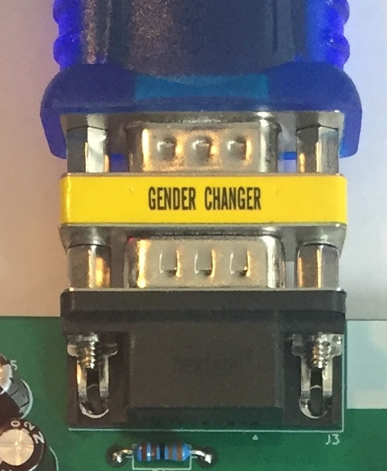
Gender changer Female/Female DB9 - https://www.amazon.com/StarTech-com-Slimline-Serial-Gender-Changer/dp/B00066HOXO
-
USB to Serial Adapter - https://www.amazon.com/gp/product/B00IDSM6BW
-
Mac or other PC - https://www.apple.com/macbook-pro
-
Macports - https://www.macports.org
-
or Homebrew - https://brew.sh
-
or whatever package system you like that works, apt, pkg, yum, etc.
-
minicom
 sudo port install minicom
 brew install minicom
 sudo apt install minicom
 ...
Planning and preparation
(skip or review if you read the keypad programming tutorial)
To program in 6502-land, there is some planning required.
First, we have to decide where our program will reside in memory. According to Appendix A of the PAL-1 manual, there are 5k memory addresses available, but looking at the KIM-1 user manual, pg 38, we see that the first 512 ($0200 hex) bytes are used for page 0: $0000-$00EE, reserved: $00EF-$00FF, and the stack: $00FF-$01FF, and anything above $03FF is expansion (labeled optional for PAL-1). So, for our example, we will stay out of the optional RAM area and for simplicity, begin our program at the first user friendly location of $200. So long as we don’t go past $03FF, we will be KIM-1 compatible. This gives us 512 bytes to play with.
Start your program at $200.
Next, we need to decide what our program will do. In this case, we will do a pretty minimal thing, we will change the contents of the A register to the value $FF and break. A more minimal program is possible, but this program has an effect that we will be able to detect.
By looking at the 6502 Programming Manual, we learn that LDA is the instruction that moves a value into the A register, and that there is an immediate mode that will let us specify the value directly. We also learn that BRK is the instruction to interrupt a program.
In assembly language mnemonics:
LDA $FF
BRK
Assembly language is great as a high level language :), but we can’t type in assembly language on our PAL-1, we need something more low level. In this case machine code is called for… So, back in the programming manual, we see that LDA has 8 different machine code representations, one for each addressing mode, the addressing mode we are interested in here, is immediate mode and sure enough, there is only one code for that mode, $A9, and that it is a 2 byte instruction, where the first byte is the code, and the second is the data to be loaded, in our case $FF. Similarly, looking up BRK, finds only one code, $00 for the implied mode, and that it is a 1 byte instruction.
In machine code:
A9 FF 00
That’s our program. It requires 3 bytes of machine code and we have it!
Next, we need to decide on what should happen when an interrupt (like our BRK) occurs. To keep things simple, we will leverage an existing functionality that the PAL-1 (or KIM-1) ROMs provide, which is the keyboard monitor, itself. We will load the interrupt vector with the location of the start of the keyboard monitor. This will cause the program interrupt to run the monitor (wait for commands from the user) - super handy!
The interrupt vector, IRQ, is located at $17FE-$17FF, the location of the start of the monitor is $1C00. We store the location LO-BYTE then HI-BYTE, this is known as little-endian order. So, in memory, this will look like:
17FE 00
17FF 1C
That’s it for preliminaries and planning. In the discussion below, keep in mind that the labels of the keys are below the keys themselves.
Configure minicom You can do this using the program itself
minicom -s
or more efficiently, you can edit the configuration by hand
sudo vi /opt/local/etc/minirc.dfl
# Machine-generated file - use "minicom -s" to change parameters.
pu pprog9           ascii-xfr -dsv -c10 -l100
pu port             /dev/cu.usbserial
pu baudrate         1200
pu bits             8
pu parity           N
pu stopbits         1
pu updir            /Users/wsenn/pal
pu downdir          /Users/wsenn/pal
pu rtscts           No
change locations to suit and that’s all we need to do to configure minicom
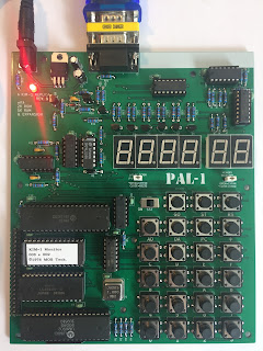
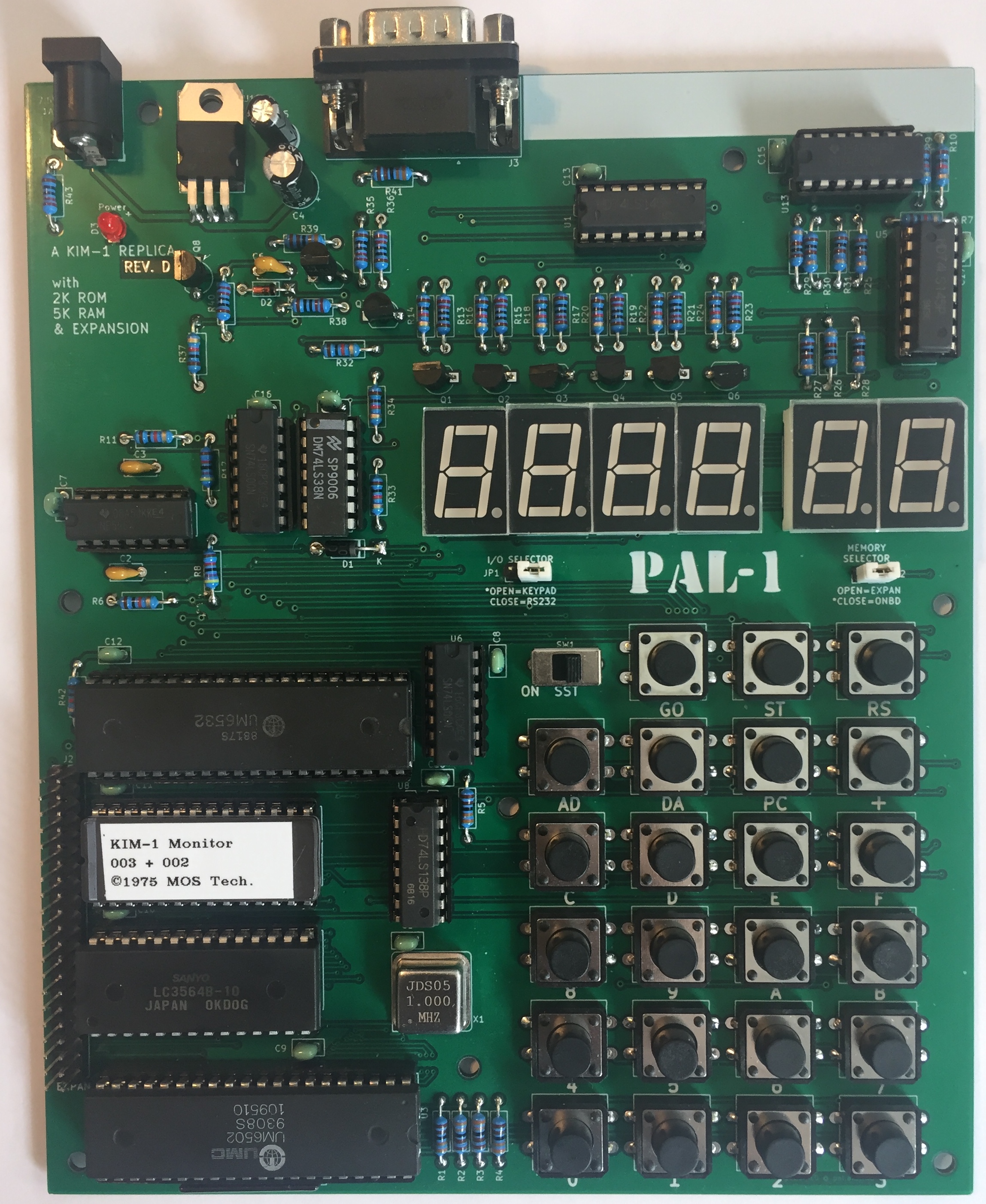
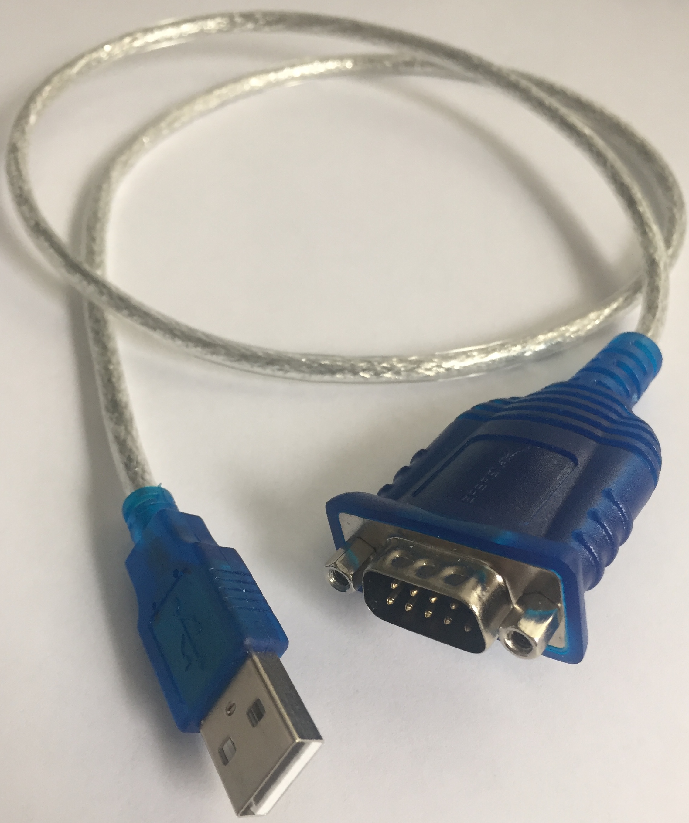
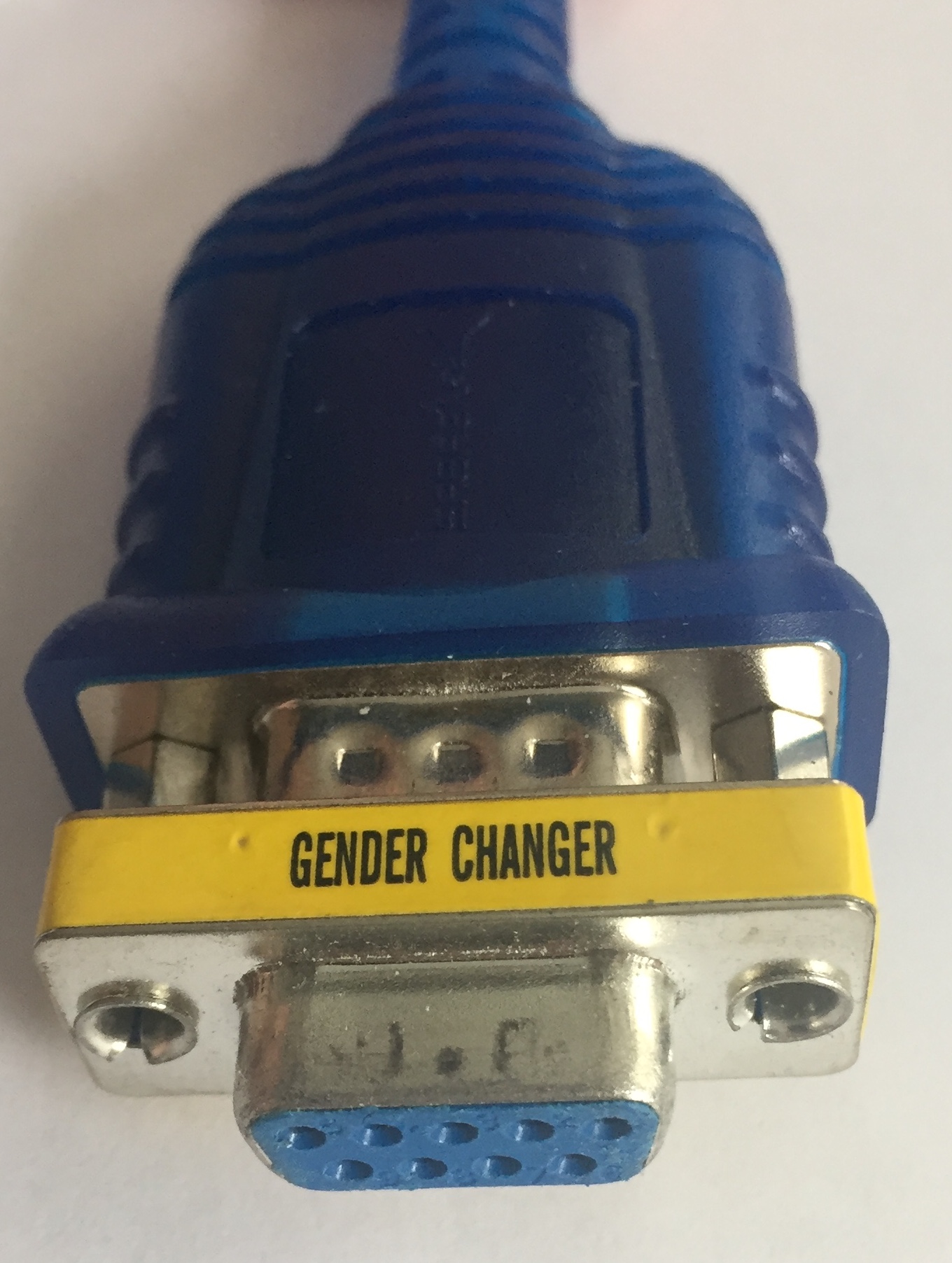
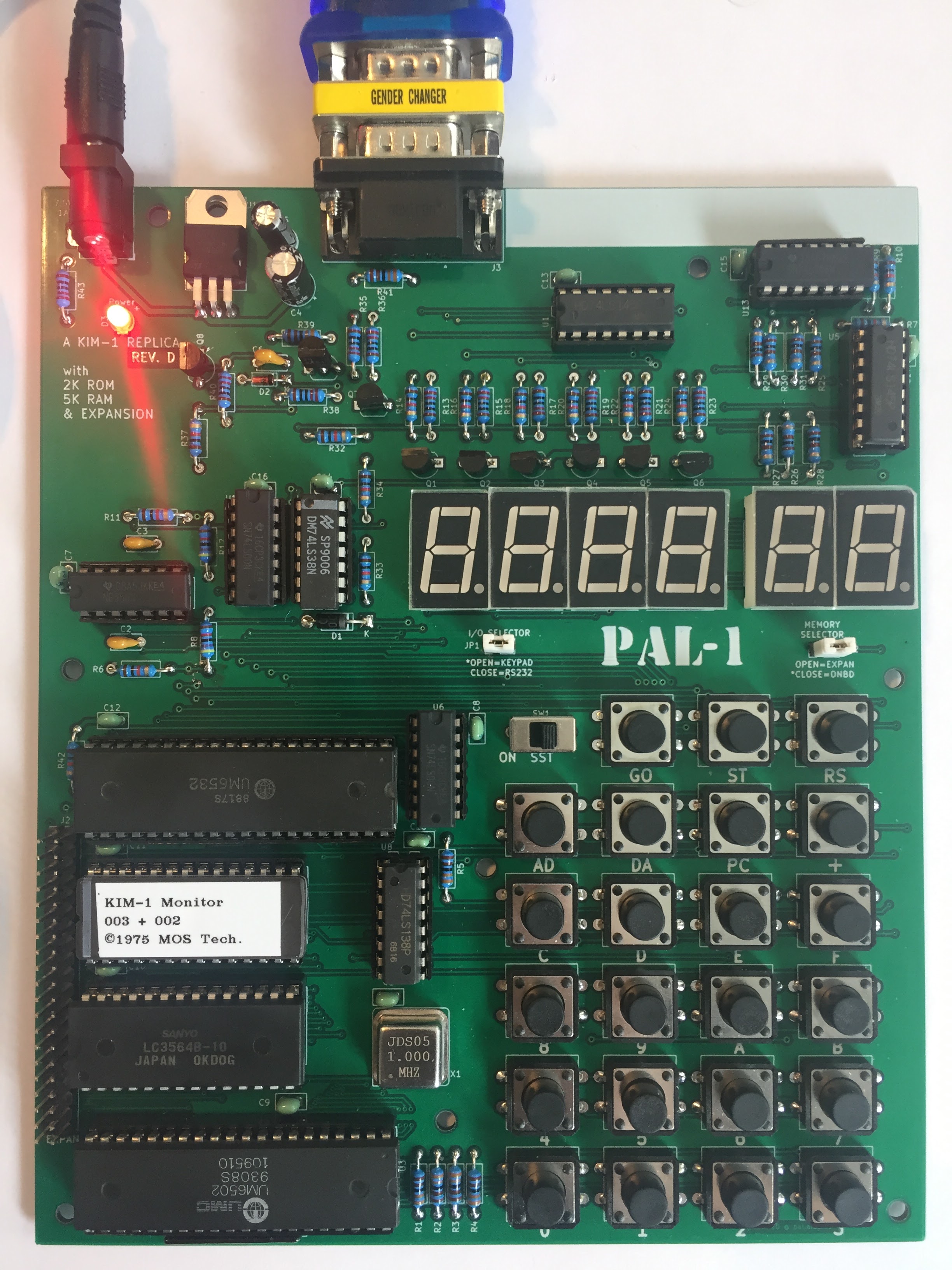
Parts and their Connections
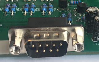
- PAL-1

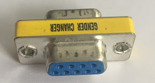
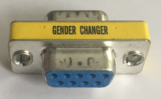
- Gender Changer (2 views)
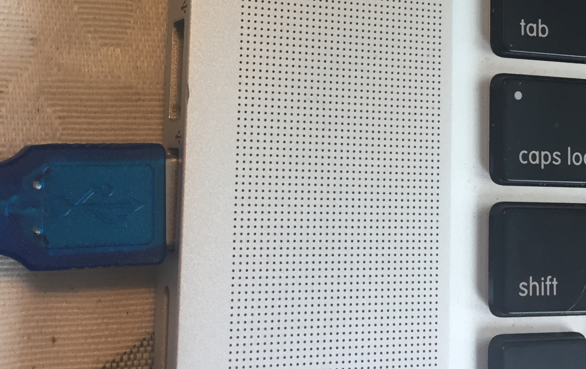
- USB to Serial Adapter

- The USB to Serial adapter needs to be connected to the gender changer

- The gender changer needs to be plugged into the PAL-1
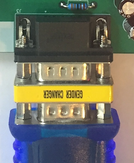
- The USB connector needs to be plugged into the computer
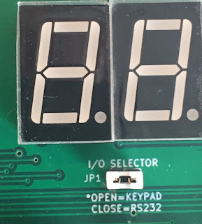
- JP-1 needs to be closed for serial operation
Once these are connected, we are ready to attempt to connect to the PAL-1 over serial.
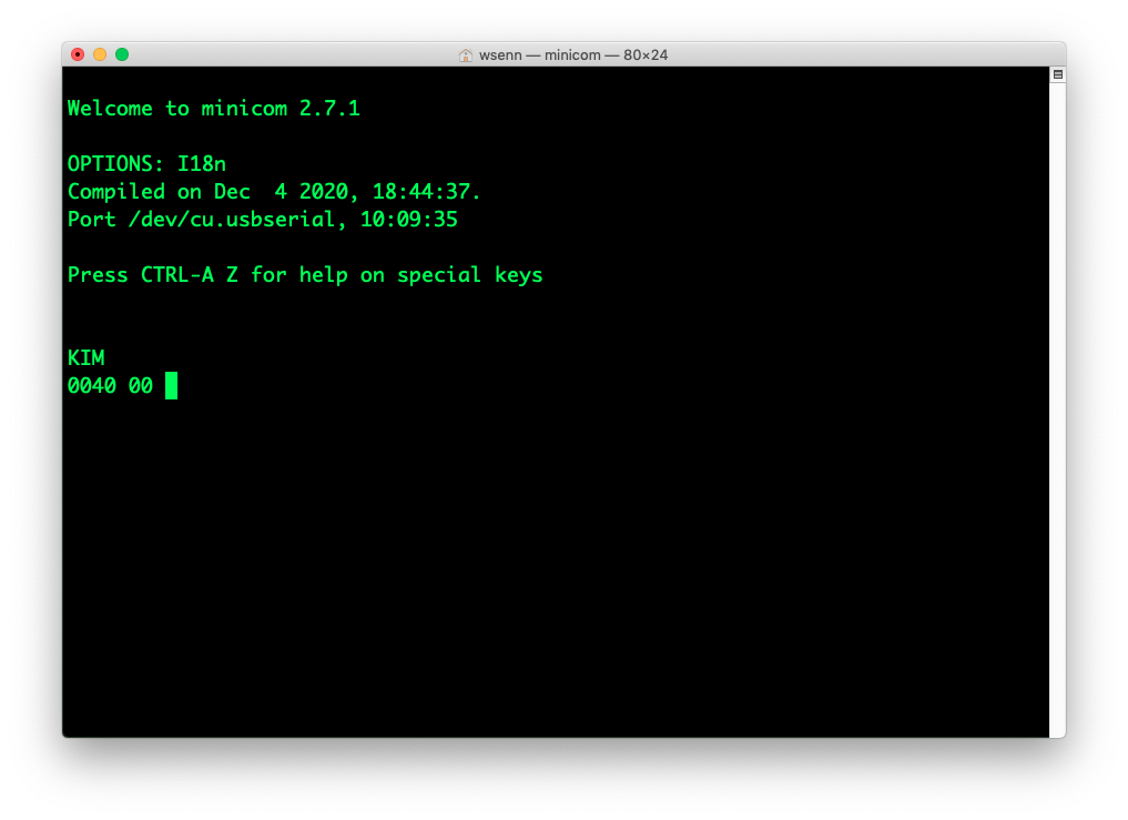
Connect
Let’s see if the PAL-1 is accessible over Serial:
-
Close JP-1 (Serial Entry)
-
Close JP-2 (Onboard memory)
-
Attach Power to PAL-1 (Power LED should light, but not he 7-segment LEDs)
-
start minicom
minicom -
Press RS to initialize the PAL-1 (pushbutton at the top right)
-
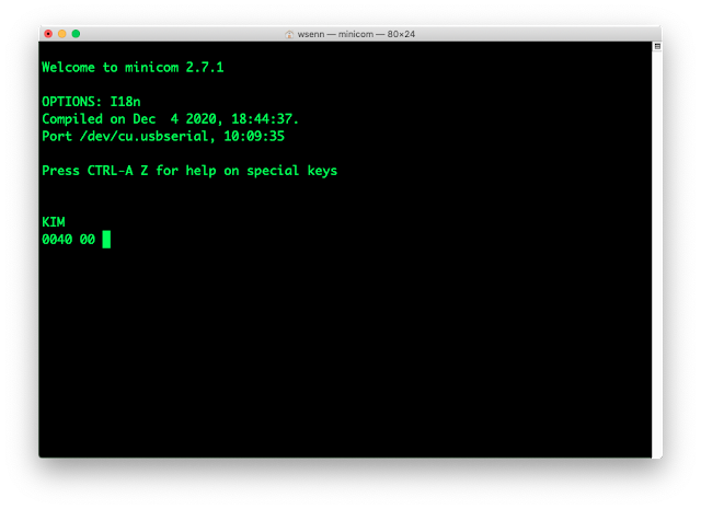
In minicom, press return (if it’s working, you will get a prompt)
Entering a program over serial is different from using the keypad. The keypad has a very limited set of keys, whereas your pc has many, many keys (only a subset are meaningful to the PAL-1, see the KIM-1 User Manual for more information). The most interesting keys are:
-
HEX DIGIT - Numbers and letters A-F (uppercase only) represent themselves
-
SPACE - after you type in an address in hex, space tells PAL it’s an address and displays that address (equivalent to pressing AD and typing four hex digits)
-
DOT - the period, after typing two hex digits, tells PAL it’s data (equivalent to pressing DA then two hex digits)
-
** - the plus sign increments the address by one and displays the data at that location (equivalent to pressing plus (+) in address mode.
-
Enter the program
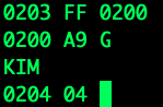
Enter the starting address of the program, in hex, 0200, then press SPACE
Enter each byte (pair of hex digits) followed by dot(.) to move to the next byte
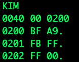
Confirm that the bytes are entered correctly
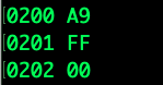
- Enter the start address of the program, 0200, and press SPACE
- Observe that the data byte displayed is A9
- Press ENTER twice and note that the data bytes displayed are FF and 00 respectively
On screen, this looks like:
and our program is in RAM, ready to run.
Set up the interrupt vector to start the monitor
We do this so that our program will run, and will return to the monitor
- Enter the Interrupt vector, 17FE (this is IRQL, low byte of IRQ) and press SPACE
- Enter the low byte of the start of the monitor and press DOT(.), 00.
- The address displayed is 17FF (this is IRQH, high byte of IRQ)
- Enter the high byte of the start of the monitor and press DOT(.), 1C.
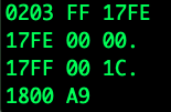
Confirm that the IRQ is properly configured (left as an exercise for the reader, see above)
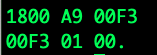
Initialize the contents of the A register before we run our program
The KIM-1 User manual tells us that the A register is mapped to memory location $00F3.
- Enter 00F3 and press SPACE
- Enter 00.
Run the program
To run a program entails entering the address where we want to start and typing G.
- Enter 0200 and type SPACE
- Type G
If all went well, the screen should display:
The program ran, was interrupted and has restarted the monitor - it is displaying the location of the Program Counter and the contents of that location. XX will be whatever was previously stored at $0204.
Celebrate!
Troubleshooting tips
If nothing seems to happen when you press G, this probably means your PAL-1 is busy doing something other than driving the LEDs. The most likely cause is that you forgot to set the IRQ to the monitor start.
To regain control of the PAL-1, press RS, then in minicom, press ENTER. You should get a prompt:

Then you can confirm memory looks like you would expect:
- Enter 0200 and SPACE
-
Press ENTER a few times
- Enter 17FE and SPACE
-
Press ENTER a couple of times
- Enter 00F3 and SPACE
If all of that looks right, then be sure that you actually started your program at 0200:
- Enter 0200 and SPACE
- Press G
If it’s still not working, get on the PAL-1 google group and ask for help - the folks there are friendly and helpful.
Links to high res images:
- pal-1 powered off
- gender changer view 1
- gender changer view 2
- usb to serial adapter
- usb to serial adapter with gender changer attached
- pal-1 db-9 serial connector - unattached
- pal-1 db-9 serial connecter - attached
- usb to serial adapter connected to macbook
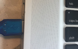
- jp-1 with jumper attached
- pal-1 powered up with attachments
- minicom talking to pal-1
post added 2022-12-02 17:31:00 -0600