Using an el-cheapo logic analyser to detect address bus activity
This note documents my exploration of using a $9.99 logic analyzer to watch my PAL-1 go through some address bus gyrations.
Planning
The program I used to exercise the PAL was from Don Lancaster’s Micro Cookbook Vol. 2 (Part 1, Part 2), Chapter 7, Discover Module 2 - Figure 8:
Write a program that starts on an even page, does nothing three times, jumps to an odd page, does nothing three times again, and then returns to the initial page.
View address line A8 on an oscilloscope.
The logic analyzer I used was this one https://www.az-delivery.de/en/products/saleae-logic-analyzer
The software I used was the amazing opensource sigrok Pulseview - https://sigrok.org/wiki/PulseView
I chose to start my program at $0200 (an even page in user RAM) and jump to $0300 (an odd page in user RAM), looking ahead to the addresses, this meant that bit 9 would be high all of the time and bit 8 would change from 0 to 1 over and over… more on this later.
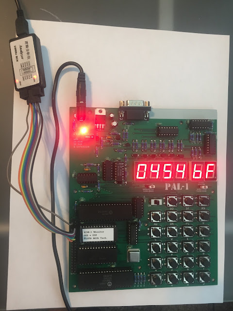
Hooking up
The Logic Analyzer came with a USB-miniUSB cable and 10 female/female jumpers. I read the PAL-1 manual and found the expansion port pinout. I hooked the jumpers up to the logic analyzer and ran them as follows:
- Logic Analyzer to PAL-1 Expansion PINS
- GND to PIN-0
- CH0 to PIN-3 (A0)
- CH1 to PIN-38 (A1)
- CH2 to PIN-4 (A2)
- CH3 to PIN-37 (A3)
- CH4 to PIN-5 (A4)
- CH5 to PIN-36 (A5)
- CH6 to PIN-7 (A8)
- CH7 to PIN-34 (A9)
I skipped A6, A7 because they should always be low during this program and I only have 8 channels!
Powered up:
Programming
The program was simple to write, starting at $0200 and jumping to $0300:
0200 NOP
0201 NOP
0202 NOP
0203 JMP $0300
0300 NOP
0301 NOP
0302 NOP
0303 JMP $0200
In machine code:
0200 EA EA EA 4C 00 03
0300 EA EA EA 4C 00 02
Since I wouldn’t be stopping the program (other than by removing power), I didn’t see a need to set IRQ or NMI to $1C00 as I normally would.
Running and Analyzing
I started up Pulseview and let it detect the logic analyzer. It found what it believed to be a Saleae Logic Analyzer, so I figured it was working.
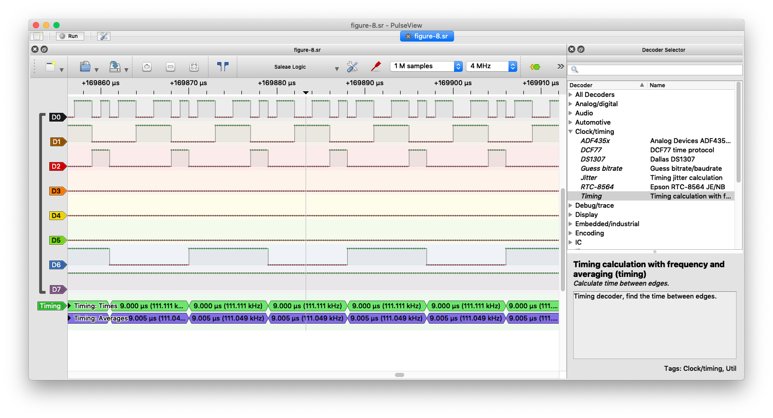
I set the sample settings to 1M samples and 4 Mhz for a 1/4 second sample. I added a timer on D6 to see how often the A8 line cycled (Lancaster said it would be 9 microseconds).
On the PAL-1 I typed in 0200 and pressed GO to run the program.
In Pulseview, I pressed Run and lo and behold, I got a readout. I zoomed in until I could read a section:
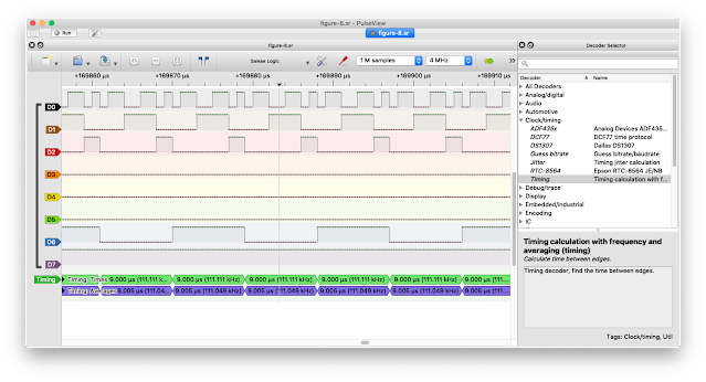
Gobbledegook, or was it? I looked at it and wondered if I could just glom its secrets, but alas, it looked like data, but what kind of data, I wasn’t sure.
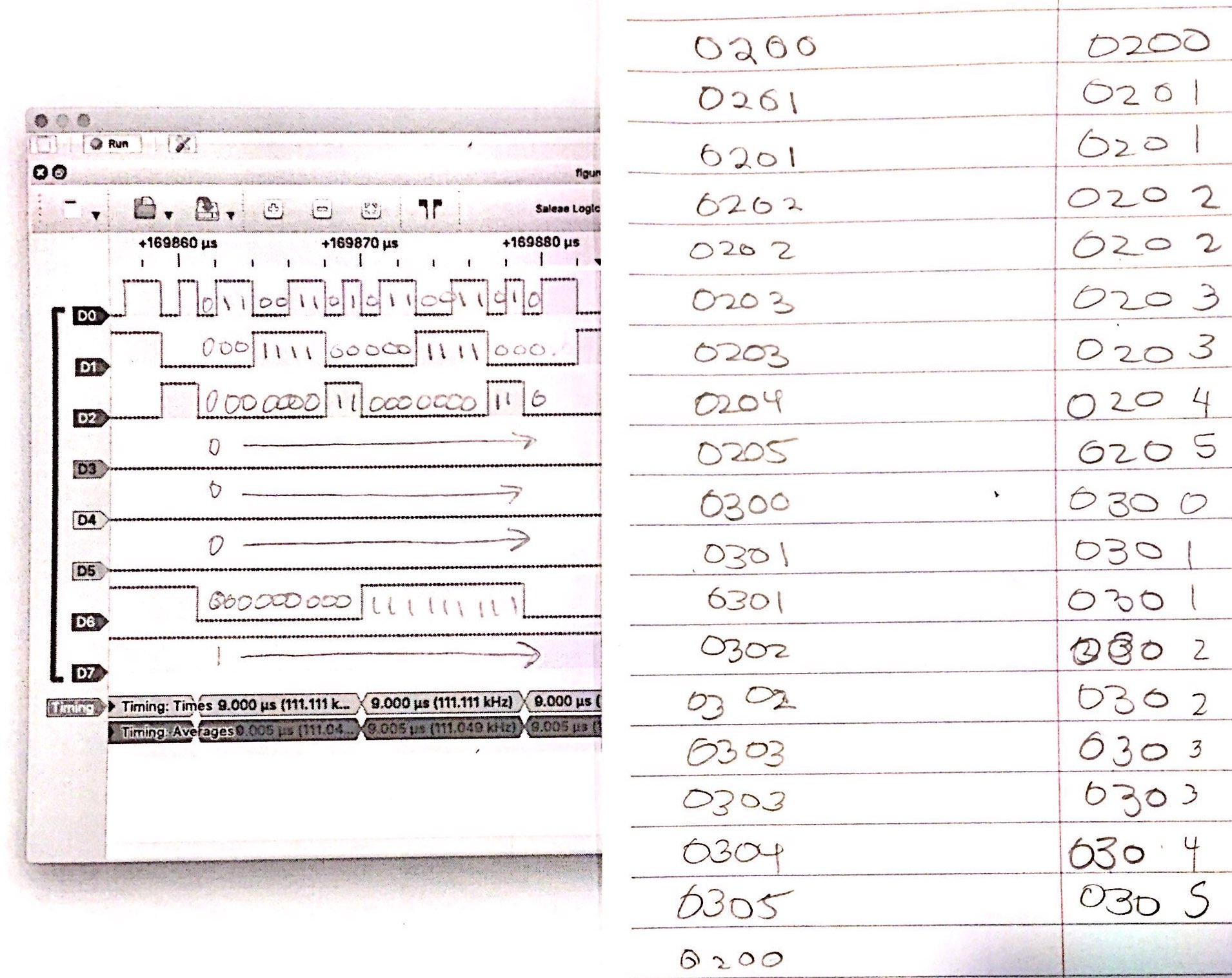
But, I thought some more, reread a bit of Lancaster’s explanation of square waves and address lines, and then I got out pencil and paper and started putting 0’s and 1’s on the readout and doing hex conversions using A9-A0 (figuring A6,A7 to be 0’s) and this is what I saw:
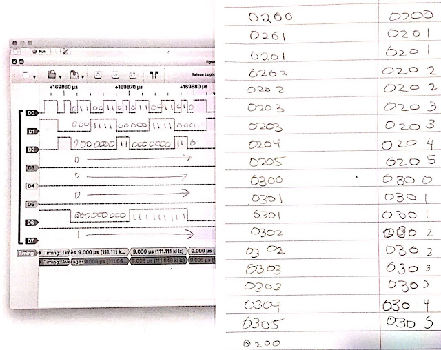
Woohoo! Numbers… my numbers! 0200…201…201…202…202…203… etc. Sure enough, just as Lancaster said it would, I was seeing the address change before my very eyes. Very satisfying.
In case you were wondering, I did confirm on a subsequent sample that indeed, A6 and A7 were held low.
I was left with one question. why are some addresses on the bus longer than others? At first I thought, maybe it’s cuz NOP’s are quicker than JMP’s, which is true, but doesn’t really explain why some NOPs seem quicker than others… 0200 is one count, 0201 is two, 0300 is one count, 0301 is two…
Ah, well, lots to learn, so little time!
Links to high res images:
post added 2022-12-02 17:52:00 -0600